| Model: VLMBN |
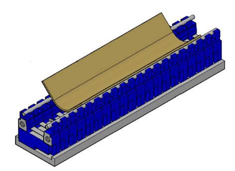
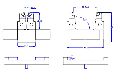
W : 25 – 125 mm
R : 8 mm
Max. Load: 90° 125 t/m
Operating angle: from 30° – 180°
Die length: 250, 500, 550, 1000 and 1050 mm |
 |
 |
|
| |
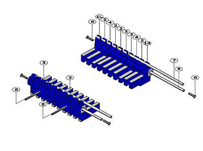
| VLMBN Assembly. |
 |
|
|
Part list VLMBN Number of parts is depending of the required length:
| 1 |
VLMBN 1R-1L |
| 2 |
VLMBN 2 |
| 3 |
VLMBN 3 |
| 4 |
VLMBN 4 |
| 5 |
VLMBN SA |
| 6 |
VLMBN nut |
| 7 |
VLMB |
| 8 |
VLMBN SS |
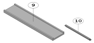
| 9 |
VLMBN Bottom holder |
| 10 |
VLMBN Spacer bar |
|
| |
|
| VLMBN Sample of adjusting. |
|
|
|
| |
|
|
|
 |
|
|
| |
|
 |
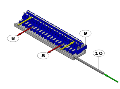
First, the securing screws (8) must be loosened until the desired spacer bar width. |
| |
|
 |
Then, the front die halves are pushed backward so that the spacer bars are freely accessible. |
| |
|
| |
|
 |
The spacer bars (10) can then be removed and replaced by the desired spacer bars. |
|
| Figur 1 |
|
|
|
| |
 |
|
|
| |
|
|
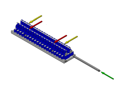
The rear die halves are then pushed against the securing screws so there is space for the desired spacer bars. |
| |
|
|
Now the new spacer bar can be pushed in.. |
|
| Figur 2 |
|
|
|
| |
 |
|
|
| |
|
|
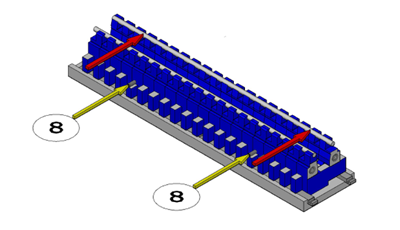
The rear die halves have to be pushed against the rear spacer bars and there |
| |
|
|
after the securing screws have to tighten softly by hand. |
|
|
Figur 3
|
|
Note:
|
|
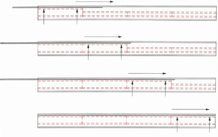
When changing from a lager spacer bar opening to a smaller one, the die halves must always be pushed on the spacer bar at each pushed-in length, so that they cannot become detached from each other
|
 |
| |